Browne Education Campus - Washington, D.C.
Challenge
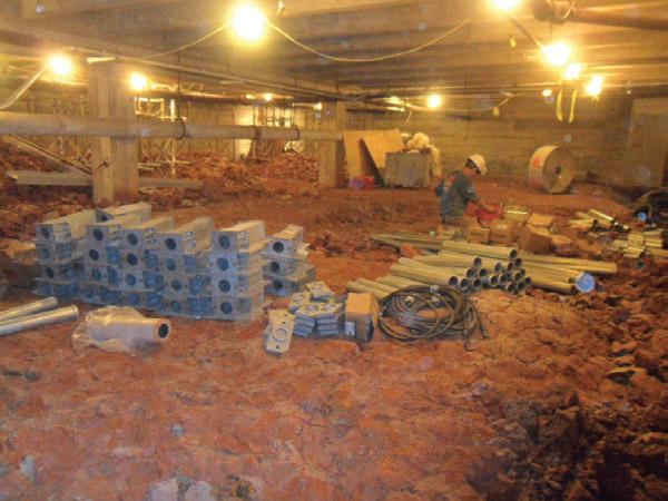
The original school building and gymnasium on the Browne Education Campus were constructed around 1920. The north and west walls of the gymnasium were experiencing differential movements, evident by cracks in the poured concrete foundation walls and cracks and separations in the interior and exterior brickwork. It was reported that a water main leak had occurred near the area of observed distress in the north wall. Test borings completed north of the north wall of the gymnasium encountered sand, silt and lean clay fill to depths of five to 8.5 feet over plastic (fat) clay to the maximum completed depths of 50 feet. A boring off the southwest corner of the gymnasium sampled fat clay from the surface to 30 feet. Excess water from the water main leak likely weakened some of the foundation soils, resulting in building settlement. Fat clay soils also experience volume changes with changes in moisture content; i.e., they will swell when wetted and shrink when dried. Some of the building movement and distress was also likely the result of seasonal wet/dry cycles of the foundation soils. The active zone for seasonal moisture variations for the clay soils in this area is believed to be seven to eight feet below the ground surface. Stabilizing the structure with traditional concrete underpinning was ruled out because of existing utilities, limited working space and shoring required for deep excavations. A deep foundation was proposed to be installed within the crawl space beneath the gymnasium floor. Helical piles could provide resistance to the design compression and tension loads for the project, but would be difficult to install within areas of limited access and head room.
Solution
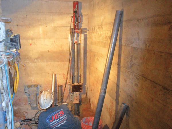
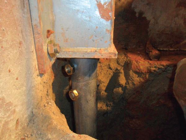
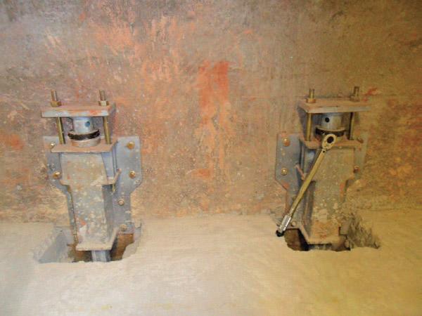
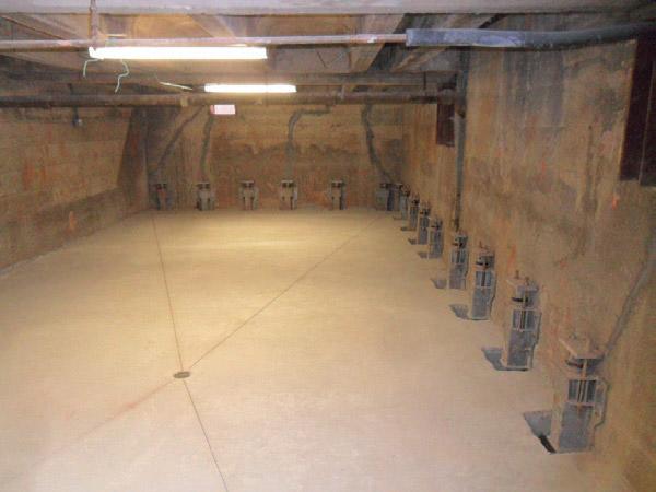
A test push pier with the standard Model 288 system was installed to evaluate drive loads and anticipated pier depths. A modified hydraulically-driven push pier system was then proposed to support the design working loads of 31 kips in compression and seven to 11 kips in tension. The uplift capacity and some of the compression capacity of the pier were calculated using side/skin friction of the pier shaft within the native soils below the active zone. The push pier tube was fabricated from FSI Model 287 helical pile shaft material (2.875-inch OD by 0.203-inch wall) with specially designed bolted couplers. Holes were cored through the 12-inch thick concrete footing at center to center spacings of three feet. Flush-mount brackets were attached to the poured concrete perimeter foundation walls with adhesive anchors. As the pier sections were advanced through the bracket, one 0.75- inch bolt was installed on each side of the coupler. The 39 piers were advanced to achieve the specified minimum depth of 30 feet and the specified minimum drive load of 48 kips. Actual depths ranged from 30 to 45 feet. Pipe clamps were placed at the tops of the piers above the brackets to resist the tension loads.
Project Summary
Products Installed: (39) Foundation Supportworks® Model 288 Push Piers (Modified), Installed to Depths of 30 to 45 feet, Design Working Loads of 31 kips (Compression) and 7 to 11 kips (Tension)