Temporary Shoring Wall
Challenge
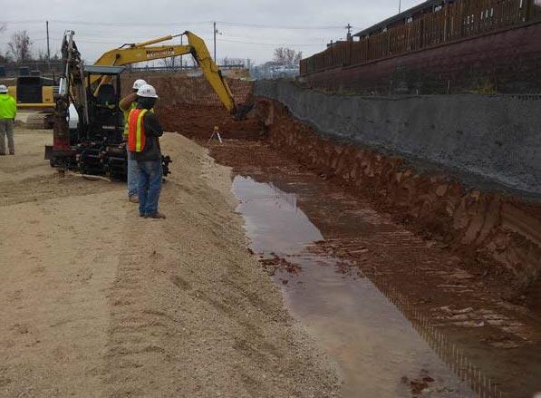
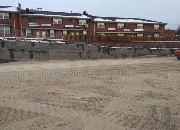
A three-story, 77,000 square-foot medical office building was planned for construction in St. Louis County, Missouri. The east area of the construction site sloped upward to the northeast to a parking lot located east of the east property line. An existing segmental block retaining wall, located along the southern half of the east property line, provided grade separation between the parking lot and the lower ground surface of the subject property. The east wall of the new medical building would be located about 10 feet from the adjacent property. The proposed excavation depths for the new foundations would require temporary shoring along an approximate 200-foot long section with estimated wall heights of about 7 feet at the south end to 12 feet at the north end. The shoring wall design would have to consider vehicle surcharge loading from the adjacent parking area, as well as surcharge loading from the segmental block retaining wall. Following construction of the medical building, engineered fill would be placed between the east foundation wall of the new medical building and the temporary shoring wall. Driven sheet piling or soldier pile and timber lagging walls were not preferred shoring options due to the vibration imparted to the soil during installation, potentially causing movement of the existing retaining wall and parking lot. Two soil borings were available for the shoring wall design which indicated that the retained soils were comprised of soft to stiff lean and fat clays extending down to limestone bedrock at depths of about 17 feet at the north end to about 10 feet at the south end.
Solution
A helical soil nail and shotcrete wall was selected for the earth retention system because of the ability to install with smaller equipment and within limited work areas, the lack of vibration during installation, and the overall cost being less expensive than other options. The approximate 200-foot long wall varied in height from about 12 feet at the north end to about 7 feet at the south end. The SNAIL software program was used to design the soil nails for a minimum factor of safety of 2.0. The final design included up to three rows of soils nails to lengths of 21 feet and installation angles of about 10 degrees from horizontal. A permanent easement was required since the soil nails extended beyond the east property line. A total of 109 Model 175 (1.75-inch solid square shaft) helical soil nails with 8-inch diameter helix plates were installed along the approximate 200-foot long wall. The first row of soil nails were installed about 2 feet or less below the top of the shotcrete wall and vertical spacings ranged from about 2 to 4 feet between rows. The soil nails were installed at horizontal spacings ranging from about 4 to 6 feet with final termination torques ranging from 8,000 to 9,500 ft-lb at the 21-foot installed lengths. The shotcrete wall reinforcement consisted of two layers of continuous 4x4-W4xW4 welded wire mesh (one at the outside and inside face of the wall). Twelve-inch square bearing plates with threaded rod and threaded rod adapters were used to connect the helical soil nails to the shotcrete wall system. A design wall thickness of 12 inches with 4,000 psi shotcrete strength was specified. The shotcrete wall was constructed in 4 to 5-foot lifts with a shotcrete cure time of at least 48 hours before excavation of the next lift.
Project Summary
Structural Engineer: Case Engineering
Geotechnical Engineer: Geotechnology
General Contractor: Holland Construction
Shotcrete Contractor: Vee-Jay Cement Contracting Company
Helical Soil Nail Installer: Foundation Supportworks® by Woods
Products Installed: (109) Supportworks® Model 175 Helical Soil Nails; Installed Lengths of 21 feet; Final Installation Torques of 8,000 to 9,500 ft-lb.


