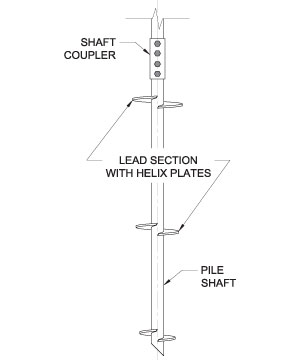
Model 350 Helical Foundation System
Specifications
Shaft Material:
- Ø3.500 x 0.313" Wall
- ASTM A572 sheet coil rolled to tube form with outside
- diameters conforming to ASTM A500 and wall
- thicknesses conforming to ASTM A513.
- Yield Strength = 65 ksi (min)
Helix Plates:
- ASTM A572 Grade 50 x 3/8" Thick (Standard)
- ASTM A572 Grade 50 x 1/2" Thick (Available)
- Helix plate geometry conforming to ICC-ES AC358.
Shaft Coupler Material:
- Ø4.250" x 0.344" Wall
- ASTM A513 Type 5
- Yield Strength = 70 ksi (min)
Shaft Coupling Hardware:
- (4) - Ø1" Grade 8 Bolts with Nuts
Finish:
- Available plain or with hot-dipped galvanized
- coating in accordance with ASTM A123.
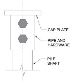
New Construction Assemblies
HP350NCB and HP350NCB8 New Construction Brackets:
- 3/4" x 6.50" Sq. A36 Cap Plate (HP350NCB)
- 3/4" x 8.00" Sq. A36 Cap Plate (HP350NCB8)
- Pipe and Hardware similar to shaft coupler.
Finish:
- Available plain or with hot-dipped galvanized
- coating in accordance with ASTM A123.
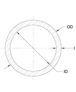
Helical Pile Section Properties
|
Nominal Thickness = 0.313 in
Design Thickness(3) = 0.313 in
- Corroded properties based on a 50-year scheduled sacrificial loss in thickness per ICC-ES AC358.
- Hot-dip galvanized coating in accordance with ASTM A123.
- Design thickness for HSS and Pipe based on 93% of nominal thickness per AISC.
|
| | Plain | Corroded Plain(1) | Corroded Galvanized(1,2) |
|---|
| OD (in) |
3.500 |
3.464 |
3.493 |
| t (in) |
0.313 |
0.277 |
0.306 |
| ID (t) |
2.874 |
2.910 |
2.881 |
| A (in2) |
3.13 |
2.77 |
3.06 |
| I (in4) |
4.02 |
3.55 |
3.93 |
| S (in3) |
2.30 |
2.05 |
2.25 |
| Z (in3) |
3.19 |
2.82 |
3.12 |
| r (in) |
1.13 |
1.13 |
1.13 |
| | Minimum Yield (ksi) | Minimum Tensile (ksi) |
|---|
| Material Properties |
65 |
75 |
|
HP350 Shaft with New Construction Bracket
| |
HP350NCB Bracket |
HP350NCB8 Bracket |
| Concrete Compressive Strength f'c(psi) |
Shortest Horizontal Distance to Edge of Concrete (inches)
|
Axial
Compression(2) (kips)
|
Axial
Tension
(kips)
|
Axial
Compression(2) (kips)
|
Axial
Tension
(kips)
|
| 2,500 |
|
4
|
44.2 |
29.4
|
53.0
|
40.7 |
| 5 |
55.3
|
36.7
|
59.5
|
42.3 |
|
6
|
66.3
|
44.0
|
66.3
|
44.0 |
|
≥ 7
|
67.5
|
43.4 |
67.5
|
43.4
|
|
| 3,000 |
| 4 |
53.0
|
35.2
|
57.9
|
41.6 |
|
5
|
66.3
|
44.0
|
66.3
|
44.0 |
|
≥ 6
|
73.4
|
44.5 |
73.4
|
44.5
|
|
| 3,500 |
| 4 |
61.9
|
41.1
|
63.8
|
43.6 |
|
5
|
72.6
|
44.9
|
72.6
|
44.9 |
|
≥ 6
|
80.1
|
46.3 |
80.1
|
46.3
|
|
| 4,000 |
|
4
|
68.5
|
44.0
|
68.5 |
44.0
|
| 5 |
78.9
|
45.6
|
78.9
|
45.6 |
|
≥ 6
|
85.3
|
46.7
|
85.3
|
46.7 |
|
|
- Capacities include a scheduled loss in steel thickness due to corrosion for black, uncoated steel. Scheduled thickness losses are for a period of 50 years and are in accordance with ICC-ES AC358.
- Allowable compression capacities are based on continuous lateral soil confinement in soils with SPT blow counts ≥ 4. Piles with exposed unbraced lengths or piles placed in weaker or fluid soils should be evaluated on a case by case basis by the project engineer.
- Capacities include limiting mechanical capacities of the shaft when the shaft and bracket are combined as a system.
- Design checks include the limiting capacities for concrete bearing which is a function of the horizontal distance to the edge of concrete. Other concrete design checks including shear, bending, and punching of the supported structure will be project specific and shall be the responsibility of the project engineer.
- This table lists mechanical capacities only. Torque-correlated soil capacities will often govern the actual installed system capacities.
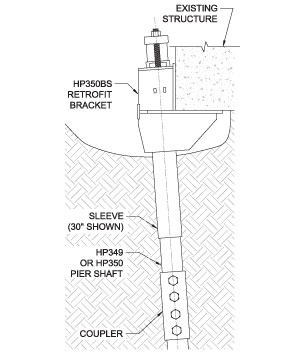
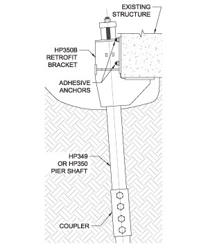
HP350 Shafts with Retrofit Brackets
 |
| | Allowable Mechanical Capacities(1,2,3) |
|---|
| |
HP350BS Bracket |
| |
30" Sleeve (kips) |
48" Sleeve(4) (kips) |
| HP350 |
44.5 |
51.5 |
|
 |
| | Allowable Mechanical Capacities(1,2,3) |
|---|
| |
FS288B Bracket |
| |
with NO Anchors (kips) |
with Adhesive Anchors (5) (kips) |
| HP350 |
36.5 |
45.0 |
|
- Brackets shall be used for support of structures that are considered to be fixed from translation. Structures that are not fixed from translation shall be braced in some other manner prior to installing helical retrofit brackets systems.
- Listed allowable capacities are based on continuous lateral soil confinement in soils with SPT blow counts ≥ 4. Piles with exposed unbraced lengths or piles placed in weaker or fluid soils should be evaluated on a case by case basis by the project engineer.
- Listed allowable capacities are for the specific shaft/bracket combination shown. System capacities should also not exceed the torque-correlated soil capacity achieved during installation.
- The use of a 48" sleeve in most cases is impractical due to the potential for coupler interference. A 48" sleeve should only be used with pier extensions of sufficient length and when the coupler location can be well controlled.
- Capacities shown with adhesive anchors utilize six Ø5/8" B7 threaded rods with Simpson AT adhesive installed to a minimum embedment of 7.5" into concrete with a minimum compressive strength f'c = 2,500 psi.
| Helical Pile Capacities Summary |
|---|
| |
Maximum Allowable Mechanical Shaft Capacities (3,5)
|
| |
Default Torque Correlation Factor (6) Kt (ft-1)
|
Maximum Installation Torque (ft-lbs) |
Maximum Ultimate Torque Correlated Soil Capacity (6,7)Qu = Kt X T
(kips) |
Axial Compression (kips) |
Axial Tension (kips) |
|
HA150
|
10
|
6,500
|
65.0(8)
|
26.5(1,8)
|
26.5(1)
|
|
HA175
|
10
|
10,000
|
100.0(8)
|
53.0(8)
|
53.0(1)
|
|
HP287
|
9
|
5,600
|
50.4
|
46.4(4)
|
23.6(2)
|
|
HP288
|
9
|
7,900
|
71.1
|
65.4(4)
|
34.1(2)
|
|
HP349
|
7
|
13,000
|
91.0
|
88.7(4)
|
50.8(2)
|
|
HP350
|
7
|
16,000
|
112.0
|
107.8(4)
|
62.5(5)
|
- Governed by AISC allowable capacity of single Ø3/4" (HA150) or (2) Ø3/4" (HA175) Grade 8 bolt(s) in double shear.
- Governed by bearing at the bolt holes.
- Capacities include a scheduled loss in steel thickness due to corrosion for black, uncoated steel. Scheduled thickness losses are for a period of 50 years and are in accordance with ICC-ES AC358.
- Allowable compression capacities are based on continuous lateral soil confinement in soils with SPT blow counts ≥ 4.Piles with exposed unbraced lengths or piles placed in weaker or fluid soils should be evaluated on a case by case basis by the project engineer.
- Listed mechanical capacities are for the shaft only. System capacities should also not exceed the installed torquecorrelated capacity or those listed in the respective bracket capacity tables.
- Listed default Kt factors are widely accepted industry standards. They are generally conservative and are consistent with those listed in ICC-ES AC358. Site-specific K t factors can be determined for a given project with full-scale load testing.
- Soil capacities listed are ultimate values at maximum installation torque. Allowable soil capacity values are obtained by dividing the ultimate values by the appropriate factor of safety (FOS). FOS is most commonly taken as 2.0, although a higher or lower FOS may be considered at the discretion of the helical pile designer or as dictated by local code requirements.
- Square shaft piles may be considered for compression applications in soil profiles that offer sufficient continuous lateral support; e.g., in soils with SPT blow counts ≥ 10. Even in these higher strength soil conditions, buckling analyses should be considered, taking into account discontinuities and potential eccentricities created by the couplers


