Gaines Street Corridor Reconstruction - Tallahassee, FL
Challenge
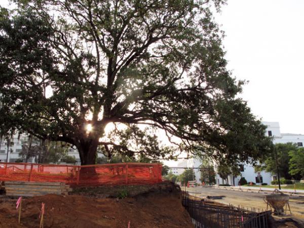
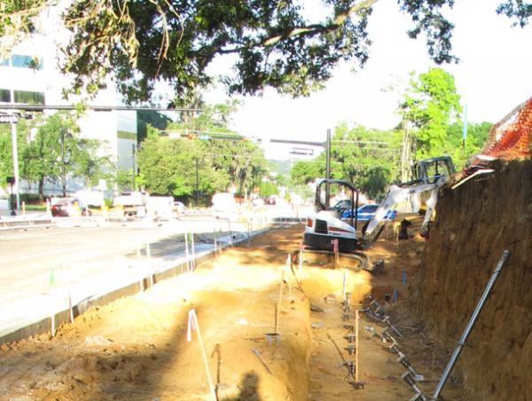
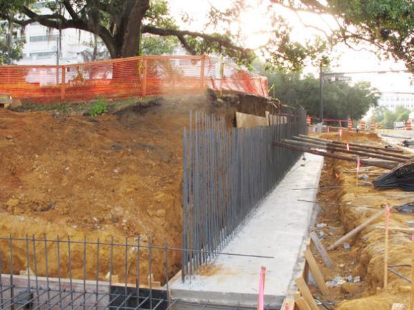
The Gaines Street reconstruction project included widening of the road to handle increased traffic volumes. However, the presence of a large oak tree northwest of the intersection of Gaines Street and Bronough Street complicated the proposed construction. The City planned to save the existing tree which was located only ten feet from the edge of the planned widening. Due to the proximity of the tree and its large root ball to the planned work, a typical cantilevered retaining wall design was not feasible. A sloped excavation or an excavation to install a segmental block retaining wall with geogrid reinforcement would also cut too far into the roots of the tree. Other design and construction considerations for the work area included overhead electric and cable lines and underground gas and water
Solution
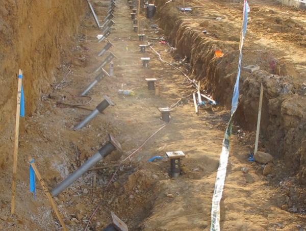
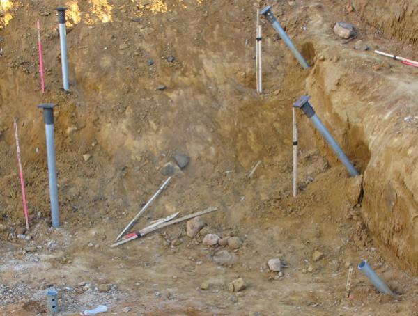
The project structural engineers decided upon a poured concrete retaining wall design with helical piles providing vertical support as well as sliding and overturning resistance. Helical piles appeared to be an ideal solution given the limited working space and low overhead conditions. Due to lack of soil information for the project, the contractor installed test piles prior to final design of the foundation to determine the appropriate helical pile configuration and depth for the design loads. The retaining wall design included 46 Model 288 (2.875-inch OD by 0.276-inch wall) hollow round shaft helical piles with 10”-12” double-helix lead sections. All piles were specified to support design working loads of 25 kips in both tension and compression. Three pile load tests were completed on nonproduction helical piles. The first was a compression test (ASTM D1143) completed 20 feet from the proposed retaining wall. A pile head deflection of only 0.098 inch was measured at the design working load. Following the compression test, a tension test (ASTM D3689) was then completed on the same pile. Even with load reversal, the measured pile head deflection at the design working load was only 0.099 inch. The third load test was a compression test completed about five feet from the end of the proposed wall. Pile head deflection of 0.043 inch was measured at the design working load. All three pile load tests met the performance criteria listed in the project specifications. Twenty-three (23) piles were installed vertically and 23 piles were installed at a 45 degree batter. The piles were advanced to provide an embedment depth of at least 14 feet to the uppermost helix plate. With installation torque values of at least 6,000 ft-lbs, torque-correlated ultimate capacities were at least 54 kips (FOS > 2). The 46 production piles were installed in two days.
Project Summary
Products Installed: (46) Foundation Supportworks® Model 288 Helical Piles, 10”-12” Lead Section, Installed to an Embedment Depth of 14 feet, Design Working Load of 25 kips