1-844-225-3917
1-844-225-3917

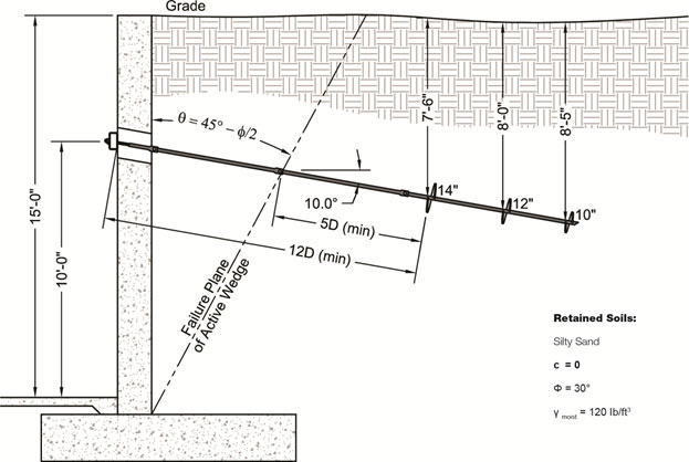
Helical tiebacks are being considered to stabilize a 12-inch thick existing reinforced concrete retaining wall. A geotechnical investigation found the retaining soils to consist of silty sand. The design engineer proposed a Model HA150 shaft (1.5-inch solid square) with a 10/12/14 helix plate configuration. The design length of the tieback was selected to meet or exceed distance criteria to the closest helix plate of 12D and 5D from the wall face and from the soil failure plane, respectively. The 14-inch helix plate was therefore set approximately 14 feet from the wall face (as measure along the anchor shaft). See the Technical Manual for more information. The soil parameters and preliminary tieback design are shown below. The engineer must determine the allowable tieback capacity so the tieback spacing can be established.
Refer to the Technical Manual for a description of the Individual Bearing Method:
Qu = ΣAh(q'Nq) ...... when c = 0
Areas of individual helix plates:
A14" = 1.05 ft2
A12" = 0.77 ft2
A10" = 0.53 ft2
Calculate vertical effective overburden pressure for each helix plate:
q'14" = (120)(7.5) = 900 lb/ft2
q'12" = (120)(8.0) = 960 lb/ft2
q'10" = (120)(8.4) = 1,008 lb/ft2
Calculate bearing capacity factor, Nq, or determine from graph in Technical Manual:
Nq = 1 + 0.56(12ф)ф/54
Nq = 1 + 0.56(12 x 30)30/54
Nq = 15.7
Calculate ultimate tieback capacity:
Qu = (1.05)(900)(15.7) + (0.77)(960)(15.7) + (0.53)(1,008)(15.7) = 34,800 lb = 34.8 kips
Calculate allowable tieback capacity using a Factor of Safety of 2.0:
Qa = 34,800 / 2 = 17,400 lb = 17.4 kips
The Model HA150 shaft has an allowable (galvanized corroded) capacity of 27.1 kips ..... OK
Refer to the Technical Manual for guidance on calculating the horizontal and vertical components of the tieback force.